 English


Wenzhou Gangyuan Electronics Co.,Ltd.
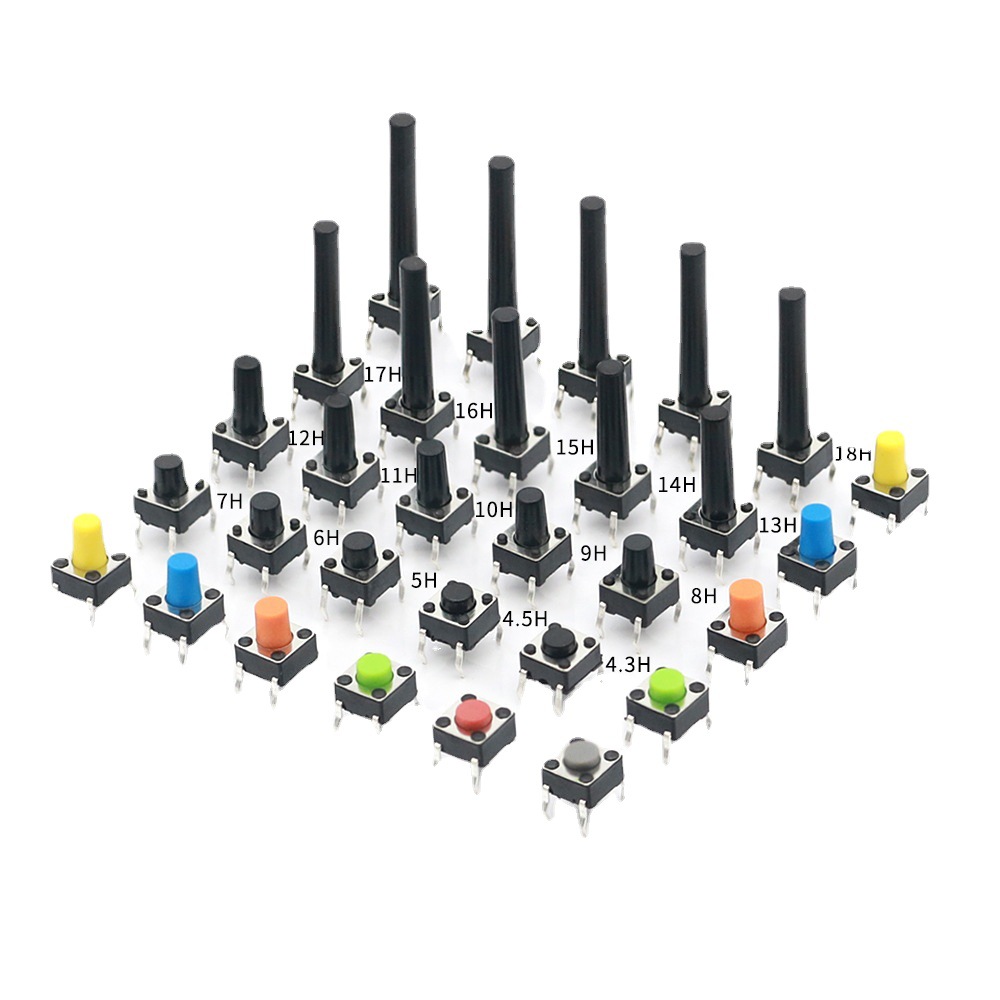
Product Selection and Specifications Q1: How do I choose the right switch type for my application (Tactile Switch vs. Non-locking Switch vs. Microswitch) ? A: This depends on your circuit's functionality and operational requirements. Tactile switches provide momentary contact—closing the circuit when pressed and opening it when released—and are commonly used for functions such as resetting or menu selection. Self-locking switches latch their state (closed) when pressed once, and reset (open) when pressed again; they are suitable for use as power switches. Micro switches typically feature a snap-action mechanism and a short travel distance, making them ideal for precise position detection or limit sensing. Please provide your voltage/current load specifications, desired mode of operation, and lifespan requirements, and we will recommend the most suitable model for your application. Q2: What is the difference between the electrical life and the mechanical life of a switch ? A: Mechanical life refers to the number of times a switch can be operated normally under no-load conditions. Electrical life refers to the number of times a switch can reliably make and break a circuit under its rated load. Electrical life is typically significantly shorter than mechanical life, as it is affected by contact arcing and material wear. When selecting a switch, please ensure that both of these life specifications meet the requirements of your specific application. Q3: A single series of switches offers a variety of mounting heights and operating forces (e.g., 100gf, 160gf, 260gf) to choose from; how should I determine the combination that is best suited for my product ? A: 1. Based on "Height"—Determining PCB Layout and Aesthetics: Low-Profile (e.g., 2.5mm): Ideal for ultra-thin devices (such as portable smart hardware and Bluetooth earbud cases); helps minimize overall product thickness while enhancing portability and aesthetic appeal. Typically features a shorter travel distance. Standard/Mid-Profile (e.g., 5–7mm): The most common choice, offering ample travel distance and operational clearance. It is easy to assemble, highly compatible, and suitable for the majority of consumer electronics and industrial controllers. High-Profile (>10mm): Designed for applications involving thicker panels or specific structural requirements, ensuring the button protrudes sufficiently through the panel for convenient operation. 2. Based on "Actuation Force"—Determining User Experience and Reliability: Light Actuation Force (e.g., 100gf): Delivers a light, responsive tactile feel. Ideal for scenarios involving high-frequency, rapid operations (such as game controllers or musical instrument keys), as it helps minimize user fatigue. However, it is important to note that an excessively light force may lead to accidental triggering under conditions of strong vibration or impact. Standard Actuation Force (e.g., 160gf): Offers an optimal balance. It provides clear tactile feedbac...
What Do Rated Current and Voltage Mean for a Switch? Can It Be Used on Higher Loads ? If you are designing an appliance or an electronic device, you have probably seen ratings like 5A 125V AC or 3A 250V AC on a switch’s datasheet. But what do these numbers actually mean? And more importantly –can you use a switch on a higher load than its rating ? In this article, we will explain the basics of switch electrical ratings and why exceeding them is never a good idea. 1. What is Rated Current ? Rated current (usually in amperes, A) is the maximum continuous current that a switch can safely carry and interrupt under specified conditions. If the actual current exceeds the rated current, the internal contacts may overheat, arc excessively, or even weld together. Common ratings for our switches: 0.5A, 1A, 3A, 5A, 10A, 16A, etc. Example: A tactile switch rated 50mA 12V DC is designed for low-power signals, not for controlling a motor or a heater. 2. What is Rated Voltage? Rated voltage (in volts, V) is the maximum voltage the switch can withstand across its open contacts and safely interrupt when opening. AC and DC ratings are different. A switch rated 250V AC may have a much lower DC rating (e.g. 36V DC or 48V DC) because DC arcs are harder to extinguish. Using a switch above its rated voltage can cause arc flash, contact welding, or even fire. Example: A micro switch rated 250V AC can be used on household appliances, but on a 125V DC system, you must check the DC rating – often only 30~50V DC. 3. Can I Use a Switch on a Higher Load (Current or Voltage) than Rated ? No. Never exceed both current and voltage ratings simultaneously. Even exceeding one parameter is risky. Here is why: Real-world example: A switch rated 3A 250V AC cannot be used on a 10A 250V AC load – the contacts will burn out quickly. It also cannot be used on 5A 125V AC, because the current is still above 3A. 4. What About Using a Switch on a Lower Voltage but Higher Current ? Still not allowed. The rated current is an absolute limit, regardless of voltage. Even if you lower the voltage, the same current will generate the same heat on the contact resistance. Example: A switch rated 1A 250V AC cannot handle 2A 12V DC. The contact resistance and heat will be the same. 5. Is There a “Derating” Guideline ? For reliability-critical applications (medical, automotive, industrial control), engineers often use a safety margin – applying a switch at no more than 70–80% of its rated current and voltage. Example: If your load is 2A 125V AC, choose a switch rated at least 3A 125V AC or higher. Derating extends switch life and reduces failure risk. 6. Summary – Quick Checklist Golden rule: Always use a switch with ratings equal to or higher than the maximum load you intend to switch.Never assume a switch can handle more just because it “looks similar. Need Help Selecting the Right Switch ? We are a direct manufacturer of tactile switches, micro switches, and self‑lock / no‑lock switches. If you are uns...
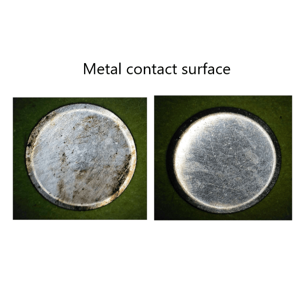
Why Do Switches Fail ? Poor Conductivity, Unstable Connection & Contact Failure – A Complete FAQ for Tactile, Micro & Lock Switches Introduction Tactile switches, micro switches, and self‑locking (maintained) switches are among the most widely used control components in consumer electronics, industrial controls, and automotive systems. Among the most frequently reported field failures are non‑conductivity (open circuit when it should be closed), poor or unstable connection, and contact failure. This article systematically explains the root causes of these failures, provides practical on‑site diagnostic methods, and offers preventive measures and selection guidelines to help engineers and procurement professionals reduce defect rates and improve product reliability. 1. Classification by Failure Mode 1.1 Conductivity Failures: No Conductivity, Poor Conductivity, Intermittent Connection Symptom A: No continuity when actuated (normally‑open contact fails to close) Common causes: Contact oxidation – This is the single most common cause. Silver contacts exposed to air gradually form an insulating film due to sulfur‑ or oxygen‑containing gases. The problem becomes critical under low‑level loads (small current/voltage) because the oxide film cannot be broken down by the weak signal. That is why gold‑plated contacts are mandatory for signal‑level applications. Flux ingress – During wave or hand soldering, flux can penetrate the switch housing through small gaps and deposit on the contacts, creating an insulating layer. Dust or foreign particles – In dusty environments, particles entering the switch obstruct contact between the dome and the fixed terminal. Permanent deformation or fatigue of the contact spring/dome – After repeated operation, the dome may crack or lose its restoring force, preventing proper closure. Symptom B: Unstable connection (intermittent signal) Common causes: Small contact area – The dome contacts the fixed terminal only at a tiny point, making the switch susceptible to vibration or slight misalignment. Vibration or shock – In high‑vibration environments, the contacts may momentarily separate. A higher operating force (OF) is often required. Arc erosion due to load mismatch – When switching inductive loads (motors, solenoids) or capacitive loads (power supplies, capacitors), the arc at opening can burn the contact surface, drastically increasing contact resistance. Sealing degradation leading to moisture ingress – Even IP‑rated switches can lose sealing if the rubber boot is damaged or the mounting is improper. Moisture mixed with arc‑generated carbon creates an insulating layer. Symptom C: Heavy actuation or need to press hard to conduct Common causes: Severe contact oxidation – Long exposure to humid or polluted air builds up a thick oxide layer that requires high force to break through temporarily. Foreign debris jamming – Dust or sticky residues inside the switch impede dome movement. 1.2 Tactile Feel & Mechanic...
1
pagesFor inquiries about our products or pricelist, please leave to us and we will be in touch within 24 hours.


 R.m 25D1, Block C, No 2070, Keji Dianzi Building, Shennan Zhong Rd., Futian Dist., Shenzhen, China
 0577-62573066
Copyright © 2026 Wenzhou Gangyuan Electronics Co., Ltd.. All Rights Reserved. Power by

IPv6 network supported


