 English




Wenzhou Gangyuan Electronics Co.,Ltd.
Tactile Switch, Micro Switch & Lock Switch FAQ: Why Poor Conductivity, Contact Failure & Unstable Connection Occur
Why Do Switches Fail ? Poor Conductivity, Unstable Connection & Contact Failure – A Complete FAQ for Tactile, Micro & Lock Switches
Introduction
Tactile switches, micro switches, and self‑locking (maintained) switches are among the most widely used control components in consumer electronics, industrial controls, and automotive systems.
Among the most frequently reported field failures are non‑conductivity (open circuit when it should be closed), poor or unstable connection, and contact failure.
This article systematically explains the root causes of these failures, provides practical on‑site diagnostic methods, and offers preventive measures and selection guidelines to help engineers and procurement
professionals reduce defect rates and improve product reliability.
1. Classification by Failure Mode
1.1 Conductivity Failures: No Conductivity, Poor Conductivity, Intermittent Connection
Symptom A: No continuity when actuated (normally‑open contact fails to close)
Common causes:
Contact oxidation – This is the single most common cause. Silver contacts exposed to air gradually form an insulating film due to sulfur‑ or oxygen‑containing gases.
The problem becomes critical under low‑level loads (small current/voltage) because the oxide film cannot be broken down by the weak signal.
That is why gold‑plated contacts are mandatory for signal‑level applications.
Flux ingress – During wave or hand soldering, flux can penetrate the switch housing through small gaps and deposit on the contacts, creating an insulating layer.
Dust or foreign particles – In dusty environments, particles entering the switch obstruct contact between the dome and the fixed terminal.
Permanent deformation or fatigue of the contact spring/dome – After repeated operation, the dome may crack or lose its restoring force, preventing proper closure.
Symptom B: Unstable connection (intermittent signal)
Common causes:
Small contact area – The dome contacts the fixed terminal only at a tiny point, making the switch susceptible to vibration or slight misalignment.
Vibration or shock – In high‑vibration environments, the contacts may momentarily separate. A higher operating force (OF) is often required.
Arc erosion due to load mismatch – When switching inductive loads (motors, solenoids) or capacitive loads (power supplies, capacitors), the arc at opening can burn the contact surface, drastically increasing contact resistance.
Sealing degradation leading to moisture ingress – Even IP‑rated switches can lose sealing if the rubber boot is damaged or the mounting is improper. Moisture mixed with arc‑generated carbon creates an insulating layer.
Common causes:
Severe contact oxidation – Long exposure to humid or polluted air builds up a thick oxide layer that requires high force to break through temporarily.
Foreign debris jamming – Dust or sticky residues inside the switch impede dome movement.
Provide your customers with simple steps to verify whether a switch is truly defective or if the problem lies elsewhere.
Measure contact resistance – Set the multimeter to the 200 Ω resistance range (or continuity mode). Measure across the switch terminals in both the free and actuated positions. A healthy switch shows stable resistance <100 mΩ. Readings >1 Ω or erratic values indicate a problem.
Visual inspection – Look for cracked housing, damaged sealing rubber, discolored or corroded terminals. White powder (oxidation product) or black carbon traces point to sealing failure or arcing damage.
Check solder joints – Cold solder joints, insufficient solder, or solder balls bridging terminals are often mistaken for switch failure.
Swap test – Replace the suspect switch with a known good unit of the same model. If the fault follows the switch, the switch is defective.
3. Preventive Measures & Selection Guidelines (From Root Cause to Specification)
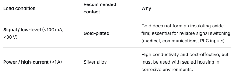
3.2 Choose the Right Sealing (IP Rating)
For inductive loads (relays, solenoids, small motors), always use an intermediate relay or contactor. Let the micro switch control only the low‑current coil – this dramatically extends switch electrical life.
If direct switching of a high‑current inductive load is unavoidable, choose a switch with a DC rating and built‑in arc‑suppression (e.g., magnetic blowout).
4. Supplementary FAQ (High‑Value Long‑Tail Keywords)
These short Q&A pairs are excellent for Google featured snippets and voice search.
Q1: Can I wash a tactile switch ?
A: Most standard tactile switches are not washable. Cleaning fluids can enter the housing, dissolve lubricants, or corrode contacts. For light cleaning, use isopropyl alcohol on a cotton swab only on the terminals, and allow complete drying. Fully sealed (e.g., IP67) switches may be cleaned locally, but always verify solvent compatibility with the seal material.
Q2: Why does a normally‑closed (NC) contact fail even when the switch is never operated ?
A: NC contacts are closed all the time. In corrosive atmospheres, an insulating film can slowly build up on the stationary contact. The only reliable solution is to specify gold‑plated contacts.
Q3: What is the difference between mechanical life and electrical life ?
A: Mechanical life is the number of cycles a switch can perform without any load – often in the millions. Electrical life is the number of cycles under rated load; it is always much lower because contacts wear due to arcing and material transfer.
Q4: Why do switches fail more often under very low loads ?
A: At higher loads, the small arc that occurs at make/break burns away organic contamination on the contacts – a “self‑cleaning” effect. Below the minimum applicable load, there is insufficient energy to clean the contacts, so oxide and contamination accumulate, leading to early open‑circuit failure.
Q5: What should I do if switches have been stored for a long time and show higher resistance ?
A: Terminals may oxidize during storage. We recommend using switches within 6 months of delivery. Storage conditions: normal temperature and humidity, no direct sunlight, no corrosive gases. Unused switches after opening the original package should be resealed in anti‑static bags.
5. Conclusion & Call‑to‑Action
Most problems related to poor conductivity, unstable connection, and contact failure can be traced to contact material, sealing, soldering process, or load matching.
By understanding these root causes and applying proper selection and handling, you can significantly reduce the field failure rate of your end products.
If you are facing a specific switch‑related issue in your design or production, or if you need assistance selecting the right tactile, micro, or self‑locking switch for your application,
please contact our technical support team. We offer free samples and application‑specific selection advice to help you improve your product’s reliability from the ground up.
For inquiries about our products or pricelist, please leave to us and we will be in touch within 24 hours.


 R.m 25D1, Block C, No 2070, Keji Dianzi Building, Shennan Zhong Rd., Futian Dist., Shenzhen, China
 0577-62573066
Copyright © 2026 Wenzhou Gangyuan Electronics Co., Ltd.. All Rights Reserved. Power by

IPv6 network supported


